The design of a 4-bit Adder/Subtractor uses a structure similar to the 4-Bit Ripple-Carry Adder.
The main differences are:
- The
C_infrom the Ripple-Carry Adder is replaced with M, which acts as a mode control signal: - When
, the bits of input B are inverted (for two's complement subtraction). - An additional XOR gate is used to detect overflow.
Block Diagram
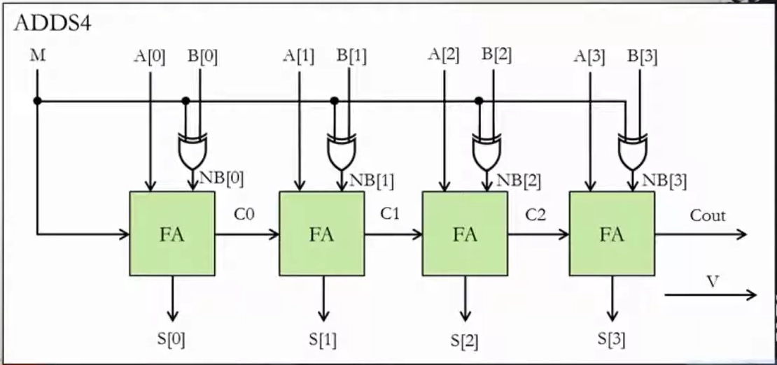
(Same as Ripple-Carry Adder, but with XOR gates between B and M for bit inversion, and an overflow detection circuit.)
Operation
- If
, the circuit performs:
- If
, the circuit performs:
which is equivalent to:
Overflow Detection
Overflow occurs if the carry into MSB and carry out of MSB are different.
So:
Verilog Implementation
Module: Full Adder.
module AddSub4(M, A, B, C_out, V, S);
    input [3:0] A, B;
    input M; // Mode: 0 = Add, 1 = Subtract
    output C_out, V;
    output [3:0] S;

    wire [3:0] NB;
    wire C1, C2, C3;

    // XOR B with M replicated 4 times for add/subtract control
    assign NB = B ^ {4{M}};

    // Full Adders
    FA FA0(.A(A[0]), .B(NB[0]), .C_in(M),  .Sum(S[0]), .C_out(C1));
    FA FA1(.A(A[1]), .B(NB[1]), .C_in(C1), .Sum(S[1]), .C_out(C2));
    FA FA2(.A(A[2]), .B(NB[2]), .C_in(C2), .Sum(S[2]), .C_out(C3));
    FA FA3(.A(A[3]), .B(NB[3]), .C_in(C3), .Sum(S[3]), .C_out(C_out));

    // Overflow detection: XOR of last two carry signals
    assign V = C2 ^ C_out;
endmodule